Simple Black-offset correction
Projector black offset correction
The goal of a multi-projection system is to create a perfectly aligned and geometrically correct homogeneous image across the projection screen. Since the images of neighboring projectors overlap, a smooth transition between the different projectors is desirable. This is achieved with edge-blending techniques which compensate for the accumulation of the luminance in these zones by gradually fading out each projector.

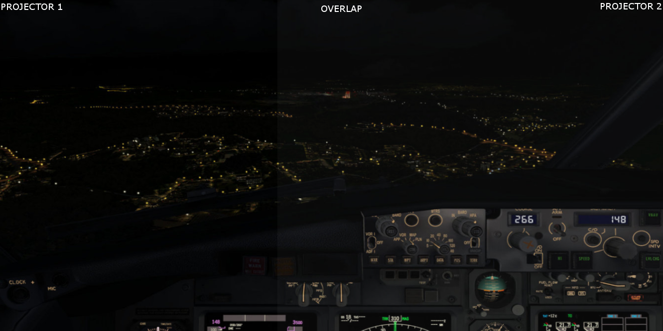
For technical reasons, most projectors are not able to reproduce a perfect black. The residual light projected by a projector for the input of zero (RGB 0,0,0) is called the black offset. Especially in the overlapping areas, the accumulating black offsets become perceptible when the displayed content is relatively dark.
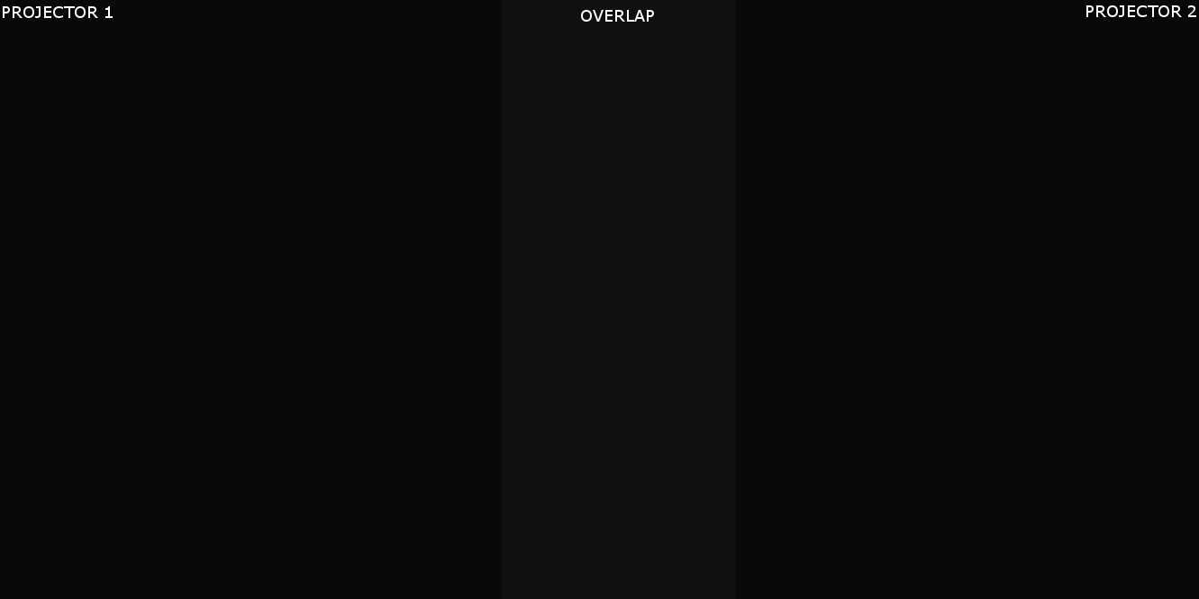
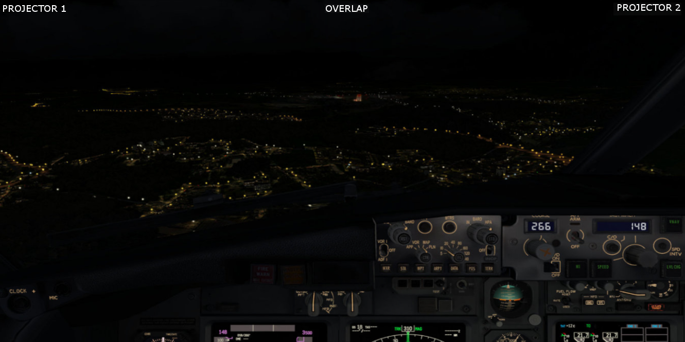
Both projectors projecting black (RGB 0,0,0) with visible black offset in the overlap
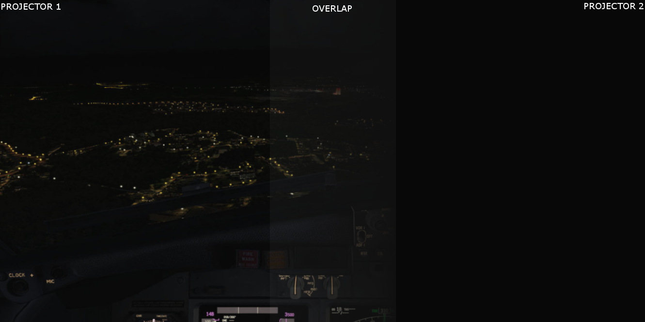
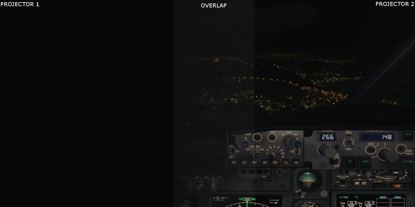
Both projectors project bark scene with visible black offset effect in the overlap.
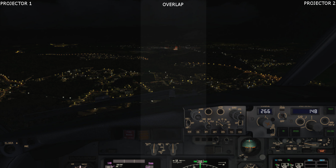
The effect of the black offset are not perceivable during the projection of lighter scenes and images.

In existing approaches for software soft-edge blending calibration, differences in the black offset are often neglected. However, with the application of multi-display solutions in a multimedia context or 3D simulation content, the importance of the black offset correction becomes obvious.
The software-only solutions for compensating for black-offset in the overlap zones modify the displayed image to adjust for the differences in the black offsets throughout the whole display. This can lead to a significant reduction of the overall the contrast and the whole image will look washed out. Hence, there is no usable software-only solution for the black offset compensation.
The best solution is to use high-quality and high-contrast projectors that have minimal black offset, and to use low-gain projection screen coating with gains in the range of 0.6 – 0.7. This will make sure that the minimal black offset will be compensated by the projection surface.
Physical shutters
Another very practical solution is by physically installing custom shutters (or shaders) in front of the projector lens, so they cover the areas in the edge blend region where there projectors images overlap.
Depending on the projectors image chip, the shape of the physical shutter can vary. Most DLP projectors have a so called “Diamond” Pixel chip. More information can be found here:
https://www.kguttag.com/2012/02/09/ti-dlp-diamond-pixel/
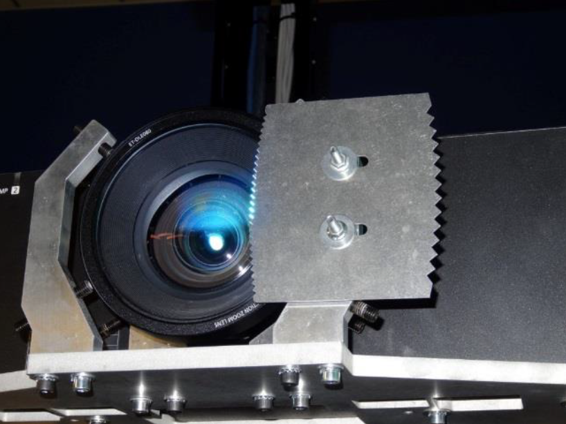
With the projectors switched on, turn on a dark dark scene or black image on your PC. Find a thick paper or a thin cardboard piece and cut a zigzag pattern on one of the ends and let the second end of the paper or cardboard be straight. Make a separate piece for each overlapped side of the projector image.
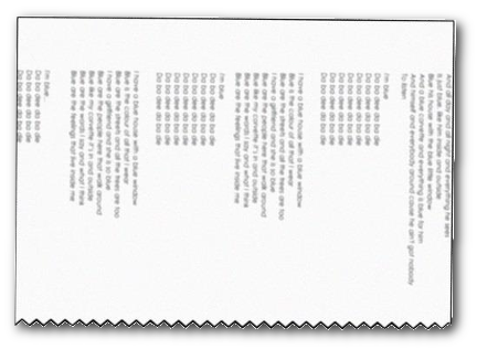
Depending on the shape of the overlap region, you may need to curve the zigzag side a little and move the shutter further away or nearer the lens. Just experiment with the position and the shape of the shutter until you get the best result.
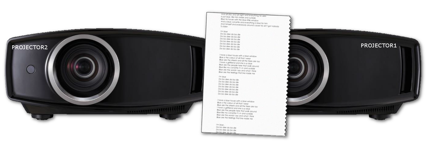
Hold the paper or cardboard in front of the projector lens and try with both sides of the paper, the zigzag side and the straight side. Choose the side which gives the best result.
Repeat this for all edge blend sides for each projector.
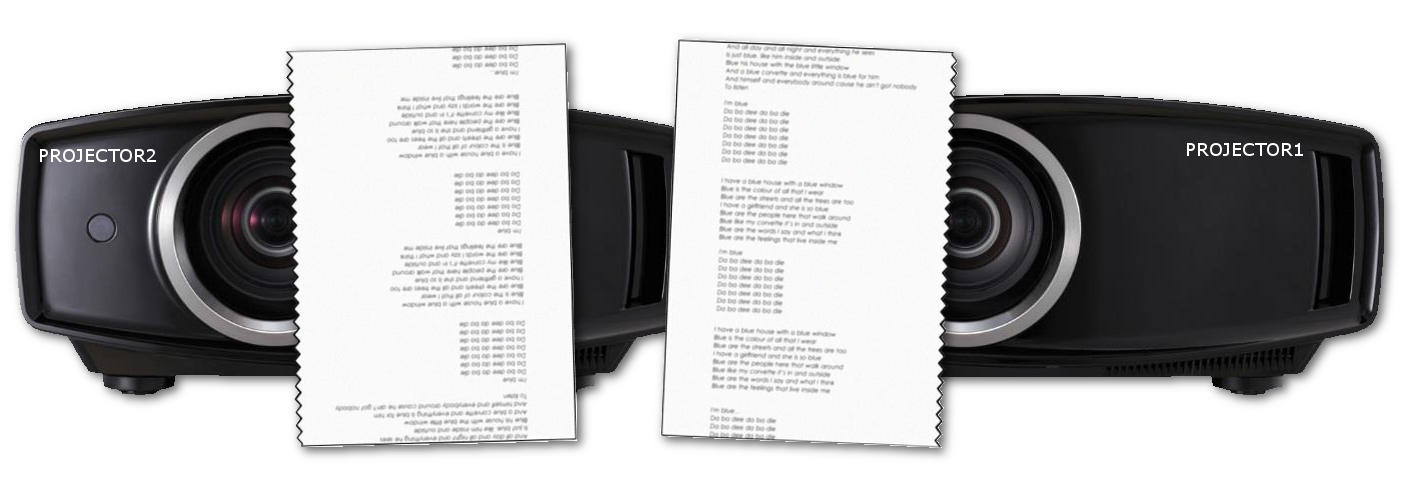
When successful, you should have no brighter black offset in the overlapped regions.
However, now you may have some brighter or darker areas when projecting bright scenes/images.

Fortunately Immersive Display PRO has blending curve editor for fine tuning the blending in the overlapping regions. Just adjust the slider so the overlapping regions are perfectly blended.
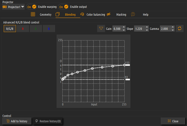
You may have to experiment with adjusting your shutters and changing between white scenes and dark scenes on your computer until you get the perfect result.
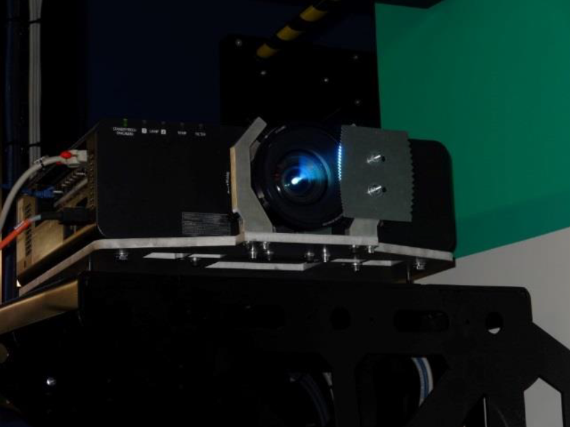
Permanent shutters
You can also chose for permanent, flexible and more robust shutter solution. This really depends on the type and shape of the projector housings. There are many different projector housings and designs. The most natural natural place to put a frame that holds shutters would be on the outer ring of the projector lens. Just make sure that the frame and the shutter do not obstruct the lens cooling air flow.
We`re here to help!
Office
Waterstad 31
5658 RE Eindhoven
The Netherlands
Hours
M-F: 8am - 10pm
S-S: Closed
Call Us
+31 40 7114293
Support
support@elise-ng.net